
Hydraulic functions for forklift attachments: count each independent movement
Define the attachment, load and operating sequence before specifying the truck hydraulics. List every movement the operator needs, identify any functions that must work together, and confirm the required control method. The truck and attachment suppliers must then align valve sections, auxiliary lines, mast hose routing, pressure, flow and connectors for the complete application.
This guide covers auxiliary hydraulics for forklift attachments such as clamps, rotators, fork positioners and side-shifting equipment.
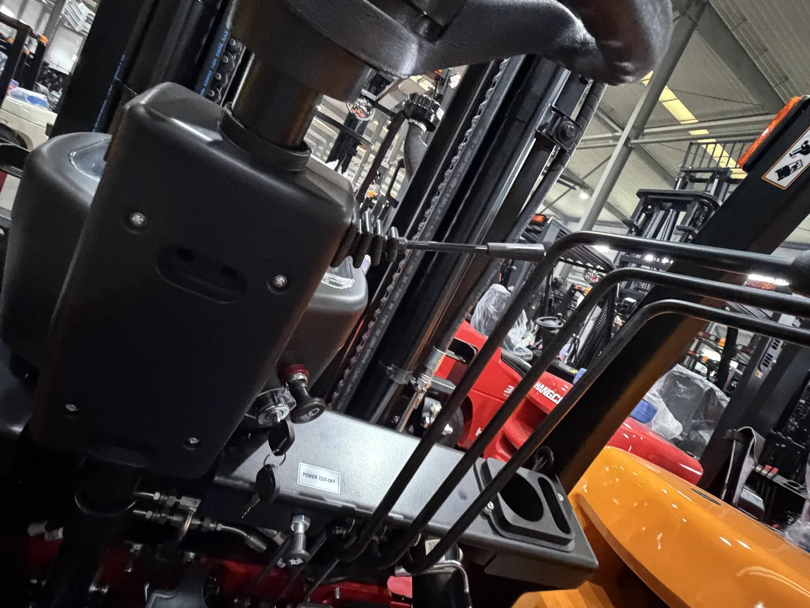
Watch attachment movements that require hydraulic coordination
This ForkFocus landscape video shows attachment movement in operation. The required valve sections, pressure, flow, hose routing and controls must be confirmed from the exact attachment function list.
Hydraulic information required before the truck is ordered
How many hydraulic functions does a forklift attachment require?
Movement list
Write each independent commanded movement and whether it must operate simultaneously
Existing truck
Identify current valves, levers, auxiliary lines, routing and fittings
New truck order
Specify attachment functions before the mast and hose arrangement are released
Pressure and flow
Use verified truck and attachment requirements; avoid assumed universal settings
Hose management
Check mast stages, full lift, tilt, carriage travel, abrasion and visibility
Controls and labels
Operator control method, function direction and handover must be clear
Plan the complete attachment function package before the truck is released
A properly configured forklift may support several attachment movements on the same truck. The hydraulic and control architecture must be designed around the complete operating sequence rather than added function by function after delivery.
Define an independent control path
Each independently commanded movement needs a defined control path. In a conventional hydraulic arrangement, another independent movement will normally add an auxiliary circuit.
Combine functions where the application requires it
Side shift, rotation, tipping, push-out, clamping or fork positioning may be combined when the truck, mast and attachment are engineered as one operating system.
Integrated controls may change the circuit layout
A verified diverter, selector, solenoid valve or attachment control block may share supply lines. The final circuit count therefore follows the approved control design, not the attachment name alone.
Check simultaneous demand
Functions used together can change the required flow, control response and hose arrangement. Confirm which movements operate separately and which must operate simultaneously.
Verify the complete hydraulic package
Confirm valve sections, controls, pressure, flow, connectors, mast hose routing, visibility and service access before quotation.
Hydraulic choices that affect attachment control and reliability
Function count, pressure, flow and hose routing answer different parts of the attachment specification.
More functions vs budget and complexity
Additional movements add valve sections or approved controls, hoses, maintenance points and cost.
One multi-function truck vs several simple trucks
Combining side shift, rotation, tipping or push-out can increase flexibility, but the full duty cycle and control ergonomics must remain practical.
Mechanical combination vs hydraulic demand
An integrated attachment can simplify handling but may require a more complex hydraulic arrangement.
Aftermarket routing vs factory preparation
Retrofitting may be possible, but access, hose protection and control integration need review.
Hydraulic-ordering errors that cause missing or unsuitable functions
Counting cylinders or relying on the attachment name does not define the required valve arrangement.
- Counting cylinders instead of independent movements
- Assuming side shift is already available
- Ignoring hose travel through a triplex mast
- Ordering attachment and truck from separate assumptions
Truck routes that can be prepared for auxiliary hydraulics
A new truck should be ordered around the attachment movement list so valve sections and mast hose routing are designed in before delivery.
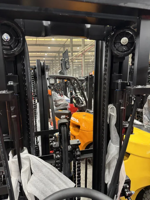
Factory or yard attachments with planned valve functions
X Series IC counterbalance forklifts · 1.5–3.8 t
Why this direction may fit: This direction may fit clamps, rotators and fork positioners when the new-truck order can specify every auxiliary line and control.
Choose another route when: Choose another configuration when the required valve sections, pressure, flow, hose travel or control method cannot be supported through the mast.
Check before quotation: List each independent movement and confirm valve count, pressure, flow, fittings, hose routing, attachment data and residual capacity.
View X Series IC counterbalance forklifts · 1.5–3.8 t
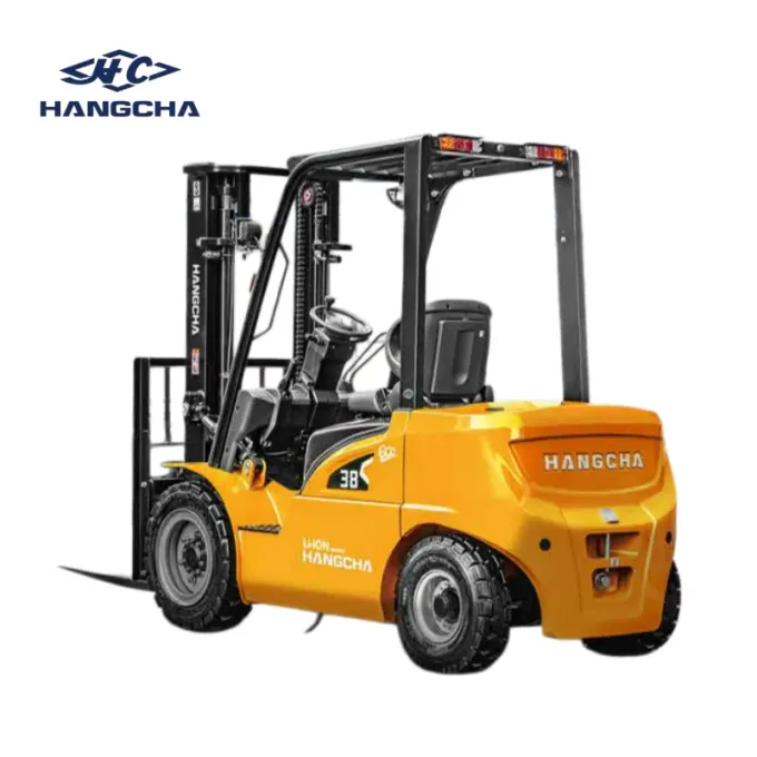
Electric attachment work with defined energy and hydraulic demand
XE lithium counterbalance forklifts · 1.5–3.8 t
Why this direction may fit: This direction may fit electric attachment work when attachment functions, charging and shift demand can be specified together.
Choose another route when: Choose another power or hydraulic arrangement when battery duty, valve availability, pressure, flow or mast hose routing cannot support the cycle.
Check before quotation: Confirm the correct capacity band, every attachment movement, valve count, pressure, flow, battery duty and attachment-adjusted residual capacity.
View XE lithium counterbalance forklifts · 1.5–3.8 t
Specify the attachment hydraulic system
Connect the required functions to compatibility, capacity, quotation evidence and model-specific service parts.
Data required for an attachment hydraulic proposal
Provide every commanded movement, the truck and mast, and the applicable pressure, flow and connector information.
Send the attachment movement list and truck hydraulic data
ForkFocus can align valves, auxiliary lines, hose routing, pressure and flow with the attachment functions.