
Forklift Rotator Configuration for Bin Dumping and Rotating Loads
Rotator configuration depends on the load or container, retention method, centre of gravity and the complete rotation and discharge cycle. The load can shift as it turns, so attachment interface, hydraulic speed, hose routing, visibility, mast loading, lift height and residual capacity must be reviewed at the relevant positions—not only with the load upright.
A forklift rotator may fit secured bins or rotating loads after retention is verified. An IC counterbalance forklift may suit a ventilated industrial dumping route when it supports the discharge height, auxiliary function, mast routing and attachment-adjusted working point.
This ForkFocus video shows a rotator turning a retained load through a dumping cycle. It makes rotation and discharge movement visible; the container interface, load retention, centre-of-gravity path, hydraulic limits and truck capacity still require application-specific verification.
Define how the load stays retained through rotation
The load's centre of gravity, retention method and discharge position change during rotation, affecting interface security, hydraulic demand, visibility, mast loading and truck capacity.
Load and container
Weight, geometry, centre of gravity, contents, fill level and potential movement.
Retention
Fork pockets, clamps, stops, locking method and condition through the full rotation.
Rotation cycle
Angle, direction, discharge height, target position, speed and cycles per shift.
Hydraulics
Pressure, flow, valve control, relief/regulation, motor requirement, hoses and swivel routing.
Truck and route
Mast, visibility, power, tyres, ground, approach and overhead clearance.
Capacity review
Attachment mass, forward offset and load-centre path at lift and rotation positions.
Trace retention and centre of gravity through the cycle
The critical position may occur during rotation or discharge, not with the load upright. Retention, clearance, speed and capacity must be checked together.
Load and container
Record contents, fill level, centre of gravity, geometry and potential movement.
Retention method
Define pockets, stops, locks or clamps that remain effective at every angle.
Discharge path
Measure angle, direction, height, clearance and receiving position.
Hydraulic motion
Confirm pressure, flow, speed, control, hoses and swivel routing.
Truck and mast
Check approach, visibility, ground, power, tyres and lift arrangement.
Critical positions
Verify capacity and stability at lift, rotation and discharge positions.
Rotation speed, retention and discharge height interact
Faster motion or higher discharge can increase load movement, visibility demand and dynamic loading; additional retention adds weight and hydraulic functions.
Faster rotation
Can reduce cycle time but may increase load movement and control demand.
Added retention
Can control the container but adds interface complexity, weight and required functions.
Higher discharge
May meet the process while reducing working capacity and operator visibility.
Rotator specifications that ignore the moving load
- Assuming fork pockets alone retain a bin during rotation
- Specifying angle without discharge position and clearance
- Combining pressure and flow into one hydraulic value
- Checking capacity only in the upright position
Routes for retained rotating or dumping loads
Use a rotator only with a verified interface and retention method; use the IC route only where the ventilated industrial duty and exact working points pass.
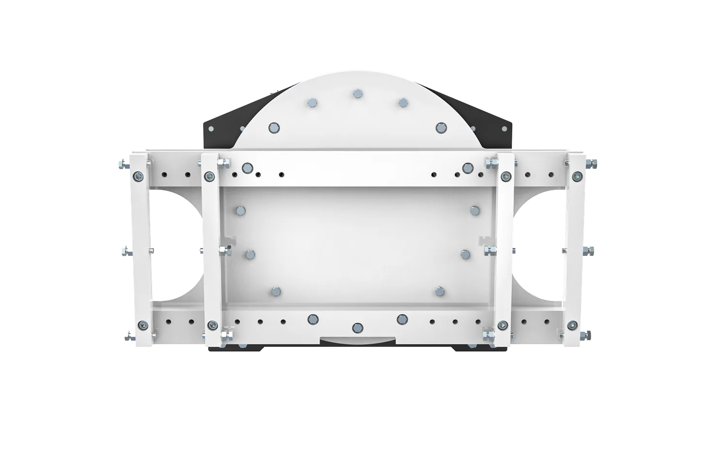
Forklift rotator
Why this direction may fit: May fit a retained bin or load when the rotation angle, interface and discharge cycle are fully defined.
Choose another route when: Use a clamp-rotator, tipper or purpose-built device when forks and verified stops cannot retain the load.
Check before quotation: Load/container drawing, retention, angle, speed, torque evidence, hydraulics and attachment data.
View Forklift rotator
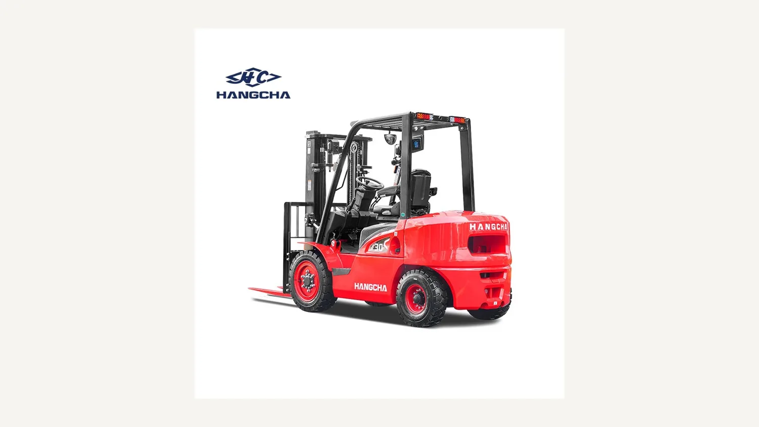
IC counterbalance forklift
Why this direction may fit: May fit ventilated controlled dumping or rotating work with adequate front access, mast clearance and auxiliary hydraulics.
Choose another route when: Review electric or another machine when emissions, reach, stability, environment, route or dynamic load movement changes the truck decision.
Check before quotation: Truck, mast, lift/discharge height, valve, hose routing, load chart and attachment moment.
View IC counterbalance forklift
Control ring, gearbox, stops and hose routing wear
The service plan should follow the actual rotation cycles and name inspection points for the mounting, retention device, bearings or ring, drive components, stops, hoses and any swivel arrangement.
- Retention and fork-pocket condition through the full cycle
- Ring, bearing, drive and stop inspection
- Hose, swivel and valve checks at all rotation positions
Plan inspection and replacement routes for bearings, gearbox, motor, hoses, seals, latches and the load-retention interface. Review the relevant ForkFocus lifecycle support.
Evidence required at every critical rotation position
Engineering review must confirm container retention, load movement, rotation speed, exact rotator data, truck mast and hydraulics, and capacity at every critical working position. Dynamic certification is not implied.
Send Your Load and Rotation Cycle
Provide the following data so the quotation can state the truck, mast, power, tyre, attachment, capacity-verification and support scope without guessing.
Send these details to ForkFocus
If the truck type is not yet fixed, use the Forklift Selection Advisor for a preliminary direction, then return with the exact mast, load chart and attachment configuration.
- Load and container drawings or photographs
- Weight, contents and centre of gravity
- Fork pockets and retention details
- Rotation angle, direction and speed
- Discharge height and receiving equipment
- Cycles per shift and environment
- Truck, mast, carriage, hydraulics and load chart
- Inspection points and service-part plan
Questions that close the Rotation-cycle configuration review
Do fork pockets alone retain a bin during rotation?
Only when the verified pocket and stop or locking design controls the bin throughout the specified angle and load condition.
Which hydraulic value changes rotation speed?
Flow primarily affects movement speed; pressure relates to available torque and component loading. Both need attachment-specific limits.
Where should capacity be checked?
Check every critical working position, including the relevant lift, rotation and discharge states, with the exact attachment and load geometry.